Username: Password:

Author Topic: Clipping diodes in a screamer clone  (Read 6229 times)

Keven

  • Lightweight
  • ***
  • Posts: 731
Clipping diodes in a screamer clone
« on: January 15, 2010, 03:22:39 PM »
hey guys, i've successfully built my second screamer clone (a GGG ITS build, gift from my girlfriend this xmas, that's thoughtful :D) and now, well, i tried the germanium diodes clipper in assymetrical formation (i think they're 1n34a but i'll have to recheck, they're the big glassy type with the green stripe) and boy, was i sorely dissapointed. the sound was nice, but the output didn't compare to the clean boost (diode lift, pure opamp distortion, wraaaa!) or the led clippers in symmetrical clipping. it was more of a pedal to clean up an OTT tube amp than a booster to make the amp go OTT. yesterday i stuck the silicon diodes in and it fixed the problems, though now there's a normal (to my ears) volume difference between led, lift and si. lift is louder, led is a bit less, and si is a bit less as well. that's fine to my ears, but Ge was REALLY quiet and barely crunchy. just a bit of dirt.

now, i wonder, is it something that could be fixed in that circuit with a future built focused on germanium diodes? i think  they clip at such a low volume that they don't give much output, but i figure that if i increase the gain after clipping, that will fix it, yes?

i'm sure some of you are familiar with screamer clones
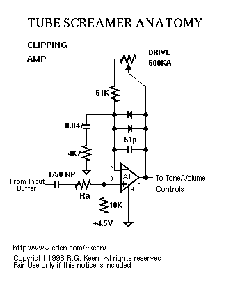
but from a discussion with a local repairman, i was led into thinking that messing with the 51k resistor could help increase the gain after the output, now, i have some limited electronics knowledge and do it for fun, and have no build to work on ATM, but what do you builders think?

or should i just forget germanium snake oil and be happy with my current screamer? or just give into geeky curiosity?
« Last Edit: January 15, 2010, 03:24:27 PM by Keven »
My BK's:
Black Dog8-Riff Raff8 / Black Dog7-Mule7
C-Bomb Set / Blackhawk Bridge
Holydiver Set/ BG50 Set

Dmoney

  • Welterweight
  • ****
  • Posts: 3577
Re: Clipping diodes in a screamer clone
« Reply #1 on: January 15, 2010, 03:35:00 PM »
i associate germanium more with fuzz pedals than tube screamers.

this might give you some more ideas
http://www.beavisaudio.com/projects/ScreamerLab/

This also has a mosfet clipping circuit you could play with which includes your diodes...
http://www.beavisaudio.com/projects/FKR/images/MightierMouse.gif


im not much help other than providing random links.
« Last Edit: January 15, 2010, 03:38:30 PM by Dmoney »

jpfamps

  • Lightweight
  • ***
  • Posts: 767
    • http://www.jpfamps.com
Re: Clipping diodes in a screamer clone
« Reply #2 on: January 16, 2010, 06:39:03 PM »
The gain of the first op amp stage is determined by the amount of negative feedback applied to that stage, and if we ignore the diodes, is set by the 4K7/ 0.047uF RC filter, the 51k resistor and the setting of the drive control.

Diodes won't conduct until a minimum forward voltage is applied to them, so at signals below this voltage the diodes won't conduct and the circuit operates as if they aren't there. Once the signal is amplified above the forward conduction threshold of the diodes then the diode conducts, thus increasing the amount of negative feedback and reducing signal gain, ie the signal is clipped.

Obviously the higher the forward conduction voltage of the clipping diodes the higher gain. The highest gain will be achieved with no diodes, as you found.

The conduction voltage of diodes can be measured with a multimeter, however this is a rough guestimate:

LED (green): 2.2V
LED (red): 1.6 V
Silicon Rectifier: 0.7 V
Ge diode: 0.4 V

As you can see the LED will give the most gain before clipping and hence less compression, whereas the GE will give the least, which is essentially what you found.

Other colour LEDs may well give different valves.

Of course you can experiment with asymmetric clipping (different diodes), using diodes in series, or using transistors/MOSFETs wired as diodes.

Musicman also used quite an interesting circuit using a combination of transisitors diodes in the feedback loop in their hybrid amps.


Keven

  • Lightweight
  • ***
  • Posts: 731
Re: Clipping diodes in a screamer clone
« Reply #3 on: January 16, 2010, 07:10:54 PM »
thanks for confirming my discoveries, i was sort of afraid i had damaged the diodes by soldering them, but then, it wouldn't have worked at all now would it?

where do you think i could do to increase the gain after clipping to retain the overall tone of the germanium compression, but with a level comparable to another od box, i'll build this one in an entirely different box so i can mod the circuit around the Ge diodes.

and i'll definitely use sockets to avoid overheating stuff :D removing the Ge diodes was a pain, since i usually install stuff so it won't have to be removed :P
My BK's:
Black Dog8-Riff Raff8 / Black Dog7-Mule7
C-Bomb Set / Blackhawk Bridge
Holydiver Set/ BG50 Set

jpfamps

  • Lightweight
  • ***
  • Posts: 767
    • http://www.jpfamps.com
Re: Clipping diodes in a screamer clone
« Reply #4 on: January 17, 2010, 04:53:44 PM »
If I change a chip on a PCB I always put a socket in (assuming there is space for a socket!).

The best way of de-soldering a component from a PCB is to a) not try to recover the part intact. Clip the leads off and de-solder the leads one-by-one (fortunately most parts in pedals are cheap), and  b) use de-soldering wick.

To boost the signal using Ge diodes, you will need an active gain stage AFTER the clipping stage. If you can live without the tone control you convert the second gain stage in the OP amp to a clean boost. You will still have an opportunity to shape the tone of pedal by swapping some other components, and you could always add a passive tone controls after the second gain stage and before the output buffer.

« Last Edit: January 17, 2010, 05:07:04 PM by jpfamps »

Keven

  • Lightweight
  • ***
  • Posts: 731
Re: Clipping diodes in a screamer clone
« Reply #5 on: January 17, 2010, 05:33:48 PM »
that's actually quite clever, i usually keep the tone control at 12 o clock anyway so i could probably live with that in a new build centered around those diodes. time to have fun with this :D

i do always use sockets for my IC's and use wick and pump, but in this build the wires are very short so it was kind of a pain to pull the PCB out of the enclosure :D.

i had the opportunity to try out this baby yesterday, in my now 15w dual EL34 head. driving the crunchy channel to searing harmonic distortion. and i can't yet decide between silicon or LED but i can see why screamers are so popular :D clips will come soon as i need to do some decent recordings of my black dogs doing low low low stuff :D
My BK's:
Black Dog8-Riff Raff8 / Black Dog7-Mule7
C-Bomb Set / Blackhawk Bridge
Holydiver Set/ BG50 Set